| June 13, 2020 |
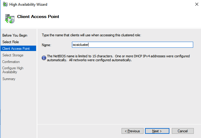
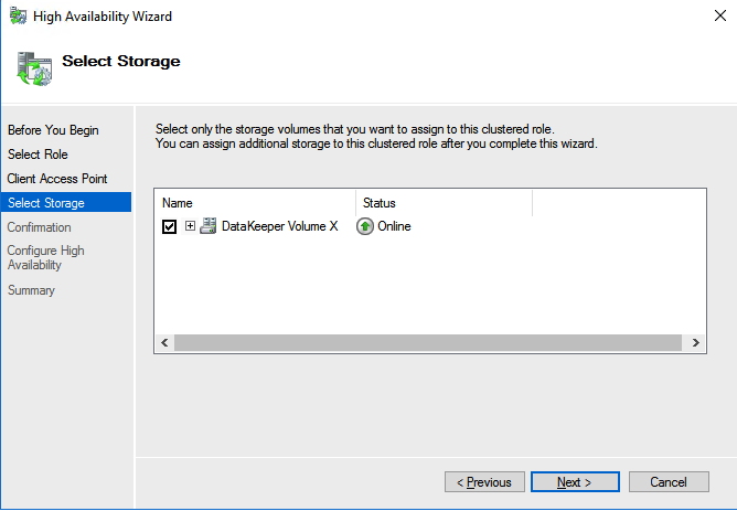
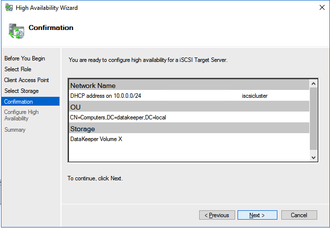
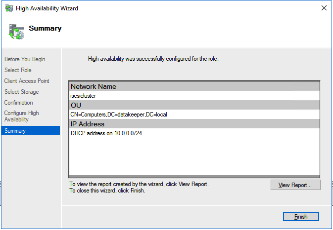
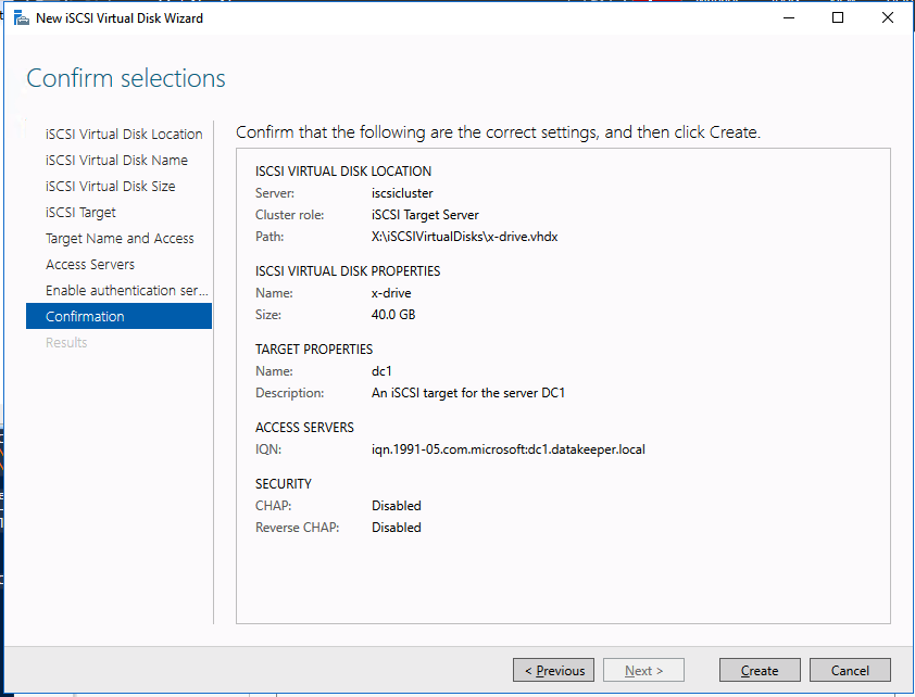
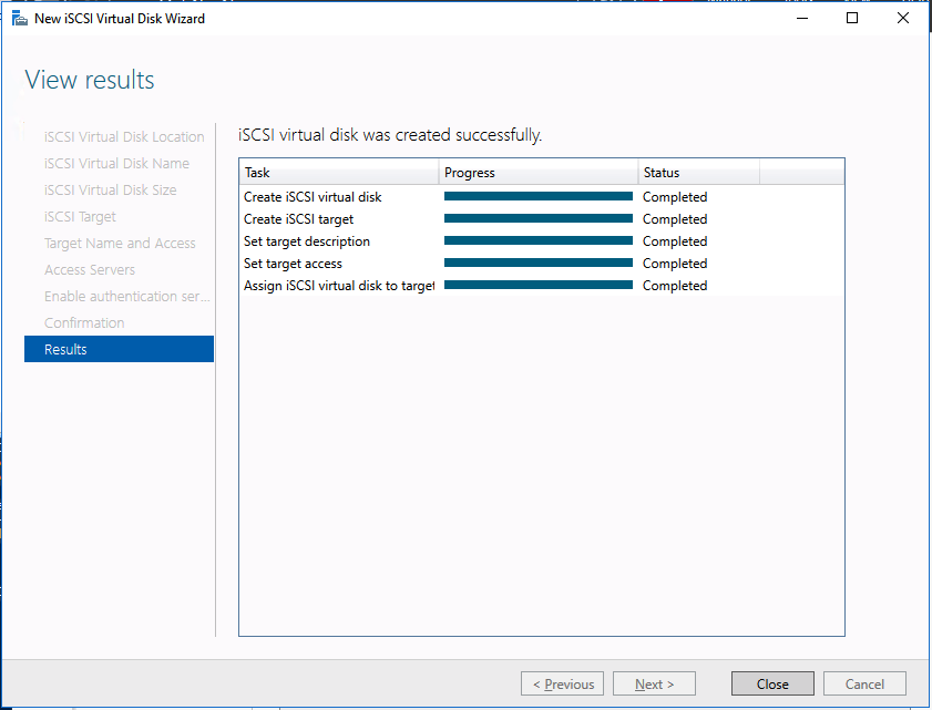
Step-By-Step: ISCSI Target Server Cluster In Azure |
| June 9, 2020 |
Solution Brief: SANless Clusters for Hybrid Cloud Environments |
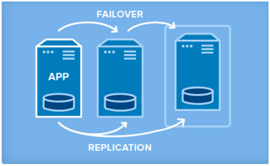
Solution Brief: SANless Cluster Solutions for Virtual Server Environments |
|
| May 17, 2020 |
Solution Brief: High Availability for SQL Server in Amazon Cloud Environments |
| May 12, 2020 |
Case Study: Chris O’Brien Lifehouse Hospital Ensures High Availability in the AWS Cloud with SIOS DataKeeper |


 Chris O’Brien Lifehouse (